Releases: Nubis-Communications/SignalIntegrity
Speedups, Bug Fixes, Series Device
This release adds some speedups, fixes a few bugs, and adds a series device
Bug Fixes
Cache Recalculation
An error was found that projects sometimes required recalculation of the cached solution, even if they had already been calculated. This bug was not commonly encountered by users and happened only for scripted solutions.
All of the tests were fixed, as well.
Features
Allow Archiving of Cached Results
When archiving, cached results can be archived as well (selectable in the preferences). Unfortunately, due to some limitations in Python, these cached results will need recalculation, unless the archive is extracted using a utility, rather than SignalIntegrity. This will be resolved in the future.
Series Device
A multi-port (even number of ports) device can be dropped into a schematic that calculates the cascade multiple times of a referenced project or s-parameter file. This is useful for converting transmission line models (that might not exactly fit the RLGC paradigm) into distributed models.
Speedups
Since SignalIntegrity is currently being used for some very large simulations, efforts were made to profile and reduce wasted time in the calculations. These are for simulations and s-parameter generation.
Python 3.11 and Clock Recovery
This release updates code and tests to ensure proper operation on Python 3.11 and adds the Clock Recovery feature
Bug Fixes
Imports on Python 3.11
Errors were found in Python 3.11 for imports. Namely, you cannot import SignalIntegrity as si and then reference the packages in SignalIntegrity.Lib. Technically this should have worked, but it doesn't. The code was corrected to do this properly.
All of the tests were fixed, as well.
Features
Useless imports removed
When users are trying to use the SignalIntegrity.Lib libraries without the GUI, the imports in the init file of SignalIntegrity was preventing desired operation. These imports have been removed, which were superfluous anyway. Closes #73.
Clock Recovery
Now, data communications waveforms can be read from oscilloscopes and the clock is recovered from the waveform. Previously, the clock was assumed perfectly related to the sample clock, and eye diagrams were just smeared messes.
Eye Diagrams can be turned off
Now, eye diagrams can be turned off, allowing the waveforms to be generated, but not the eye diagram. This helps when performing long simulations and tuning.
Documentation and Help System
While still not perfect, all of the features are up to date in both the software documentation and the help system.
SignalIntegrity moves to Nubis Communications
This release is the first release since SignalIntegrity was moved to Nubis Communications. Signal Integrity is now a Nubis Communications supported open-source tool.
Bug Fixes
Test Fixes
Previously, the unit tests could fail based on the order they were run. This was a frustrating problem that existed for quite a long time. This problem has now been fixed.
Zero Length RLGC Transmission Lines
These now work properly and don't cause an error.
Dramatic Speedup for Port Reordering
Port reordering now runs much faster due to lack of extensive copying.
Variables with Spaces
Variables values can now have spaces (mostly for strings) and are now handled properly by enclosing the strings in quotes.
Features
Logarithmically Spaced Frequency Points
During some PDN analysis work, it became painfully obvious that the low frequency aspects dictate very small frequency resolution and therefore lots of frequency points to perform the simulation. An attempt was made to mitigate this by introducing solutions that are made on logarithmically spaced frequency points (a much smaller number of points) and then resampling them at the end onto a linear frequency scale for convolution in simulations. This didn't work perfectly (and it still doesn't), but the feature is added (experimentally). You can try this out by setting the preference that allows this in the projects.
Reference Impedance for Solutions
Previously, all solutions were performed in a 50 ohm reference impedance. Any devices read in, were converted to 50 ohms. If the desire was to have a result in a different reference impedance, this could always be accomplished by post processing, converting the result to whatever reference impedance was desired. Now, the user has the capability to specify the reference impedance to perform the solution at. All devices are converted to the user specified reference impedance for the solution.
Parallel Devices
A new two-port device was added that calculates a device that is the equivalent of a defined two-port s-parameter device placed in a parallel arrangement multiple times. This is useful for parallel pins on connectors, parallel wire bonds, and parallel bypass capacitors -- it greatly simplifies these calculations.
Added COM defined Two-port Transmission Line
A device that implements the IEEE COM definition of the transmission lines has been added, which enables the user to build complete COM package models and PCB traces.
Ignore Missing Other Waveforms
Waveforms whose results are read from the disk during simulation can now be ignored if they are missing, allowing the simulation to continue normally.
Added Cache Control for Variables
Some variables, when changed, should not require recalculation of the entire solution. Now, users can declare variables that should not be in the cache definition.
Encryption and Bug Fixes
Bug Fixes
Import Errors
Closed #71 LineCollection
Previously I had tried to import Matplotlib as late as possible to avoid some other problems and did this incorrectly. When users selected variable line width, the program became unusable. This has been fixed.
Transfer Matrices
Not really a bug, but transfer matrices were unable to be computed in a simulation if the waveforms were not available. Now they can be computed without the waveforms.
Splines
These were really slow using home-grown spline software. Now this uses the scypi splines, which are much faster. This improves the time in complicated resampling operations.
Features
Encryption
The encryption feature allows encryption of SignalIntegrity projects and s-parameters. Now, in the preferences, there are two additions:
- encryption password - defaults to None
- file ending for encryption - defaults to $
if project files are saved that end in the ending specified, and there is a password, the project file is encrypted. If any encryped file is read, it is decrypted with this password.
passwords for decryption and encryption are overridden, and explicitly stating the password on the commend line using the --pwd option when invoking SignalIntegrity. The password provided on the command line is passed down through projects that are included in the project file. This allows for complete encryption of nested projects, including their s-parameters, for deployment in systems that use SignalIntegrity for simulations or calculations in other programs.
Control Changes
Now, shift-select instead of control-select is used for multiple selections, like most software. Control-select now immediately opens the part properties, which is more convenient.
DC Waveforms
These can now be shown in simulation results.
Causality Enforcement
Now, an option exists to enforce preservation of the DC point during causality enforcements. While this is not always the best thing, it is definitely the best thing when performing PDN analysis. Not preserving the DC point causes IR drops to be miscalculated.
Bug Fixes and Progress Bar
Bug Fixes
Caching
Previously, there were cases involving schematics with variables and equations (newly added features) that caused sub-schematics to not be recomputed. This has been fixed.
Archiving
Previously there were rare cases that the resulting archive would be broken in that referenced files within the archive were referenced incorrectly. This has been fixed.
Features
Progress Bar
Up until now, the progress bar showed the progress of the calculation of the top level schematic. This meant that in deeply heirarchical projects, the progress bar was frozen as the calculation gathered up s-parameters calculated from sub-schematics. Now, the callback function is passed down to nested subprojects and the progress of the calculation of these subprojects is shown. This allows the user to see what is actually being calculated, where the calculation time is being spent, and the GUI thread is no longer blocked. Furthermore, calculations can now be aborted when the calculation is being performed on these subprojects.
See Installation for installation instructions.
Equations in Schematics
Features
Equations
This release adds equations to schematics. For example, here is a schematic that uses a wirebond model:
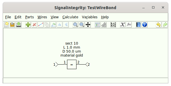
Note that the schematic specifies a length L, a diameter D, and a material gold for the wirebond.
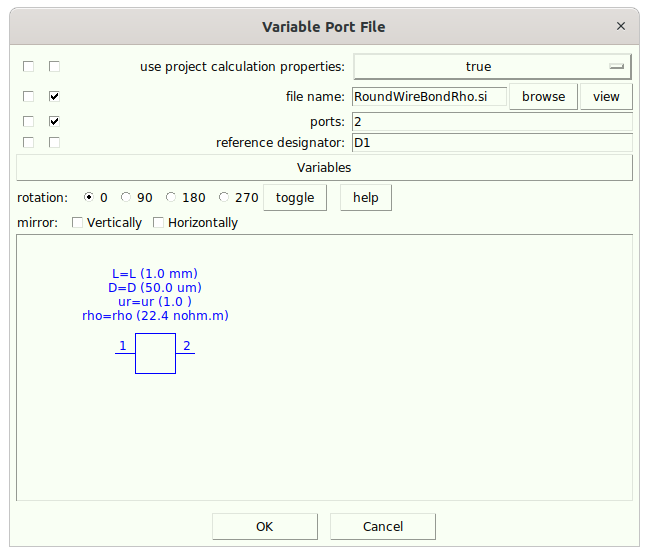
Looking at the referenced device:
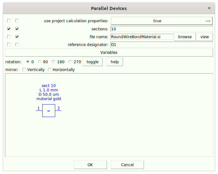
and opening the referenced file:
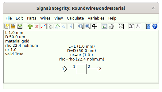
we see that it has variables associated with the schematic L, D, material, and rho, ur, and valid.
Opening the schematic variables, we see these variables:
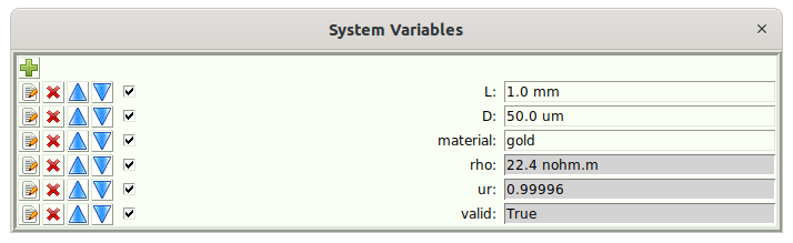
but the variables rho, ur, and valid are read only (they are what are called output variables).
Opening the script with the button that shows f(x), we see the script that converts the input variables to the output variables:
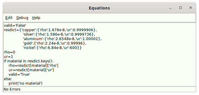
The script takes only the material and determines the relative permeability (ur) and the resistivity (rho). These are variables on the device in the schematic:
Again, we view the referenced device:
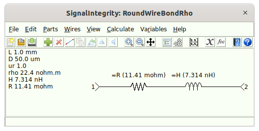
Here, we have the final wirebond model with the associated inductance and resistance. Again, looking at the schematic variables:
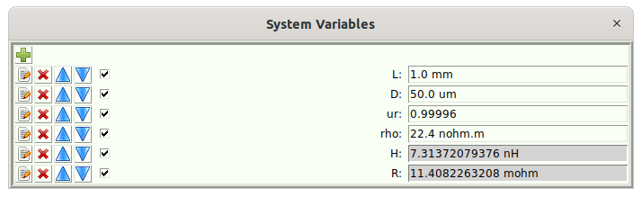
and the script:
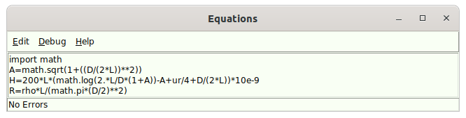
We can see how this inductance and resistance was calculated.
Have fun with this new feature!
Minor Features
Level Annotations to Eye Diagrams
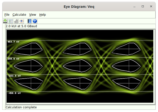
These are available from the eye diagram properties dialog.
Long Text in Device Properties
With the advent of all of the schematic variables in the last release, some very long text in device properties is possible, which really makes the schematics ugly. In the preferences you can select for the numbers displayed in floats, and for the maximum size of text in the properties. For example:
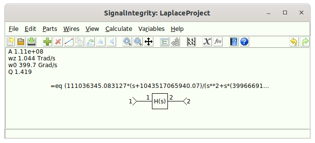
Note that the long equation now ends in ...
Bugs
Many minor bugs were fixed that are not worth mentioning.
See Installation for installation instructions.
Schematic Variables, Archiving, Eye Diagram Measurements
Features
Schematic Variables
This is a long awaited and hugely valuable feature, especially for hierarchical projects and scripted applications. Now, a schematic has 'variables'. Devices within the schematic can derive their settings from these variables. Devices which access other projects can also have variables and these variables are passed down into the nested project. In the future, schematic equations will be added that can compute new variables.
The UI handling of these variables will be improved in the future, but for now, is good enough.
Calculation properties in nested projects
Devices that reference other projects can now pass the calculation properties along so that the nested projects inherit these calculation properties.
Eye Diagrams
Sampled Waveforms
Now it is possible to view the sampled waveform containing only the samples taken at the eye diagram alignment point. This is useful for qualitatively viewing the goodness of the communications from the waveform perspective and for generating residual errors in the sampling.
Eye Diagram Measurements
Signal power, noise, residual error, SDR, SNR, and SNDR are now calculated and displayed.
Eye Waveforms (and Regular Waveforms) Added to Simulation Results
Eye waveforms and regular waveforms can now be dropped into a schematic whereby they are added to the waveform and eye diagram results without any simulation -- the waveforms are simply read from the disk and processed. Closes #22.
Optical Measurements
Optical measurements are added to the eye diagram measurements. These are measurements of input and output power, transmission penalty, insertion loss, extinction ratio, etc.
Archiving
An archiving feature has been added for dealing with deeply hierarchical projects. When projects are archived, all of the elements and projects referenced by a schematic are gathered into a directory structure, with the schematics changed to point to these newly located elements and zipped. In this manner, projects can be archived and moved easily.
Headers in S-parameter Files
Headers can now be displayed, edited, and written in post-processing steps.
Lossy Ideal Transmission Line
Ideal transmission lines with skin-effect and dielectric loss can now be used.
PDN Analysis Features
I've been using the tool a lot for analyzing PDNs, and have added a number of features, mostly to speed up these analyses that require typically very high frequency resolution
Multi-port Tees
Every area in a schematic that contains a multiple device port connection was previously implemented as a three-port tee per three port connection, followed by an additional three-port tee connected per extra device connection. This could be a lot of three-port tees, and therefore very large matrices. Now, at the parser level, if I know that there are many device connections, all device connections are made with a very large tee element connecting to all of the device ports. This greatly speeds up the calculation of these types of systems.
Parallel devices
In PDN analysis, it might often occur that many pins of a connector are placed in parallel, and many on-die capacitances might be put in parallel. This could bog down the simulator. Now, there is a specific parallel device that can put any two port device in parallel. This also greatly speeds up the calculation.
Resampling Errors
This is an enormous fix for a problem that mostly only occurs with PDNs. Inside the simulator, all calculations are performed using 50 ohm s-parameters. The ideal reference impedance for a PDN is something like one ohm. The reference impedance itself is not much of a problem, but resampling the s-parameters in the wrong reference impedance could be disastrous. This is a complicated topic, so I'll not completely explain it here, but now, all s-parameters are resampled in their reference impedance prior to conversion to 50 ohms. This means that in sub-schematics, you can set the reference impedance and make sure that the impulse and step response settles in that reference impedance, and rest assured that they will be resampled in that reference impedance. This allows PDN elements to be sampled sufficiently and analyzed for sufficiency of sampling with as few frequency points as possible, and know that it will operate properly in the simulation.
Source waveforms in results
Now, a voltage or current source can be placed raw in to the resulting simulation without having to add a probe. This eliminates the need for a transfer characteristic calculation, which is superfluous and takes unneccesary time.
Minor Features
S-parameter postprocessing
Offset Removal
offset can be removed from the impulse responses of s-parameters. This helps remove any tilt that occurs in the step response due to various problems with s-parameters (including DC point restoration).
Writing Waveforms as .csv
Waveforms can now be saved in .csv format as time, value. Closes #60
Speedups
Probe Calculation Control
To speed things up, probes can now be turned on and off. This allows probes to be placed into a schematic, but disabled until they are really needed for diagnosis or debugging.
Caching
Cached results have been trimmed to use less disk space and to open more quickly.
S-parameter Calculation
These are sped up using some more intricate linear algebra. It turns out that, at the time of my book writing, this simplification feature was already present in symbolic results, but was not carried over to numeric results. It was relatively easy to drop this optimization in. Basically the speedup is to essentially trim away parts of the network that are not interacting with ports at all, thus simplifying the computation.
Schematic Output
Schematics can now be saved as .png files.
Bug Fixes
Two-port Current Sources
A bug that caused the current direction to be invariant to the orientation of the part has been fixed.
Eye Diagrams
Jitter and Noise
Jitter and/or noise is now applied to eye diagrams, even when some (but not all) of the values are zero.
SI units
Engineering notation is no longer used with dB or dB-like units.
Reference Impedance Errors
These are now shown with an error message.
Calibration Standards Documentation
Updated to correctly document units for standards.
Opening S-Parameter Files
Previously, when opening an s-parameter file directly, if a project file was similarly named, it opened the project file. This is now fixed.
Caching fixes
Caching has been improved, especially when moving projects between Linux and Windows machines by properly sorting the netlist prior to generating the hash, and by maintaining the Linux style directory structure. In some projects, cached results were being constantly recalculated.
See Installation for installation instructions.
Eye Measurements, Bathtub Curves, and Improved Eye Diagrams
Features
This release, feature-wise, is all about eye diagrams, eye measurements, and bathtub curves
Eye Diagram Improvements and Annotations

Many eye diagram improvements were made in this release:
- The drawing of the eye diagrams are improved through the use of an enhanced precision mode. (see the User's Manual for more information.)
- The eye diagrams can now be annotated with measurements made on the eye.
- Previously, the eye diagram configuration was handled globally, which made it very difficult to deal with schematics containing multiple eye probes. Now, the configuration is unique to each eye probe.
- Eyes can now be resized easily just by resizing the window.
- Eyes can now be auto-aligned through a fairly complex algorithm that allows for alignment using vertical and horizontal criterion.

Eye Measurements
Eye measurements come in two forms:
- Horizontal/Vertical -- measures things like eye height, eye width, linearity, RLM.
- Error Rates -- measures SER, BER, etc. on both uncoded and Gray coded symbols.


Bathtub Curves

Bug Fixes
Capacitor Devices with ESR
This was really screwed up, and is now fixed.
Dialog Issues
This was not perfectly fixed, but large attempts were made to make dialogs modal, when they needed to be, and to not be resizable, if it didn't make sense, and especially not minimizable, when other dialogs were waiting for them to close. It's not perfect, but much better.
Minor Features
Post Processing
A post processing command is now supplied to change the reference impedance to whatever is desired. This makes it so that the result of the calculation immediately pops up in the desired reference impedance.
Frequency Log Scale
Frequency response and content can now be viewed on a logarithmic scale.
Converting Parts
By selecting a part in the schematic, you can now right-click on it, and convert it to another part. All of the common fields are copied over and the missing fields are set to default -- but it's still easier than placing another part down and entering everything.
Open S-parameter Viewer Standalone
Now, s-parameter files can be opened with SignalIntegrity and they open the viewer directly, without the underlying project. Windows machines can even be configured such that double-clicking on an s-parameter file can open in SignalIntegrity.
Caching of Eye Diagrams
The caching mechanism has been extended so that eye diagrams are cached. This means that when changing various eye diagram properties usually does not require recalculation of the underlying eye diagram bitmap (which takes most of the time).
Help System and Unit Tests
The help system was completely updated with the documentation, especially for the eye diagrams and all unit tests were run and passed.
See Installation for installation instructions.
Eye Diagrams, Impulse Response Filters, Transfer Matrices, and LeCroy Waveforms
Features
Eye Diagrams
Added the Eye Probe which produces very nice eye diagrams

This capability will be enhanced in the future towards items like clock recovery and measurements made on eye diagrams. For now, it assumes a single specified baud rate, and you must control the delay to center the eye in the diagram automatically -- but it does make beautiful pictures.
Impulse Response Filters
A type of filter has been added that allows for a filter to be described by the impulse (or step response of a waveform).
LeCroy Waveforms
Up to now, the only format for waveforms usable with SignalIntegrity was the SignalIntegrity text based waveform format. Now, LeCroy waveform format (the kind used in LeCroy scopes is available). These waveforms have the .trc extension and are automatically read in properly and a preference has been added to allow saving in this format as the preferred format. This is useful when using SignalIntegrity along with the oscilloscope.
Closes #5.
Transfer Matrices
The SignalIntegrityAppHeadless API that is used for driving project calculations from other Python scripts has been enhanced to allow Simulation projects and Virtual Probe projects to supply only the transfer parameters (or transfer matrices). These, as you might know, are the banks of filters to which the waveforms are applied. Also, the main application allows for calculation and viewing of only the transfer matrices (this was previously possible only after an entire simulation was performed).
Other Small, Miscellaneous Things
Upper case file names are now allowed in s-parameter files. This was not really a problem on Windows machines, but was problematic for Linux machines. Plus, some old VNAs would automatically write wave forms with upper case extensions. This is now handled properly.
The default preferences have been updated so that on new installations, The preferences are the preferred ones (previously, these were the safest ones). This means that SinX interpolation, calculation caching, and grids on plots is now preferred, along with the experimental "Try SVD" in calculations that has been around for a long time and seems to work very well.
The Laplace function filter has been updated to allow for z-domain waveforms (in addition to functions based on f, jw, and s, previously).
Bug Fixes
Waveform Adaption
During waveform adaption, there was a bug that was rarely encountered that caused the fractional delay to not be applied. This is fixed.
Documentation Fixes
Some documentation used with the online software documentation that is automatically generated from the decorated code was repaired.
Skin-effect Resistor
This feature released in the last release was very broken, and is now fixed.
Performance Improvements
It was discovered that the impedance peeling capability added awhile ago for port peeling and de-embedding was running all the time, even when peeling was not being asked for. This did not result in a wrong answer, but added a large amount of work to s-parameter generation and de-embedding, especially for large amounts of frequency points. Now, this is optimized to do as little work as possible when impedance peeling is not desired.
Help System and Unit Tests
The help system was completely updated with the documentation, especially for the eye diagrams and all unit tests were run and passed.
See Installation for installation instructions.
Minor Fixes and Features
Features
Linear Vertical Scale in S-parameters
S-parameters can now be viewed on a linear vertical scale. The usefulness of this feature is primarily evident when viewing transfer parameters in PDN analyses. For example, if you drive a PDN with a current source and probe the PDN voltage rail, the transfer characteristic is one of V/A = ohms. Therefore, when viewing the transfer characteristic on a linear vertical scale, the readout is in PDN impedance in ohms.
Headless Simulations and S-parameter Calculation Callbacks
Now, when performing a simulation or s-parameter calculation in a "headless" mode (when opening a project and running the project from a script), a callback function can be provided. This is useful to track the progress of the calculation from a script.
Relay contacts increased to 17
so that a 16 contact relay with a common can be used.
Skin-effect Resistor
A resistor device has been added where all of the resistance is due to skin effect (i.e. has a resistance specified in ohms/sqrt(Hz)).
SOLR calibration with no thru provided
Previously, a thru standard estimate was required for SOLR calibrations. Now, it is possible to let the algorithm determine the thru with no estimate provided. This should only be used with highly sampled s-parameters.
Bugs
Resampling in VNA Calibrations
When performing VNA calibrations, the measurements were not being resampled, which is a bug. This meant that the measurements provided must be on the exact same frequency scale as specified in the project in order to work. This has now been corrected and the measurements are resampled onto the project frequency scale.
See Installation for installation instructions.